Projects
Please press on the button to view the project!
The Problem
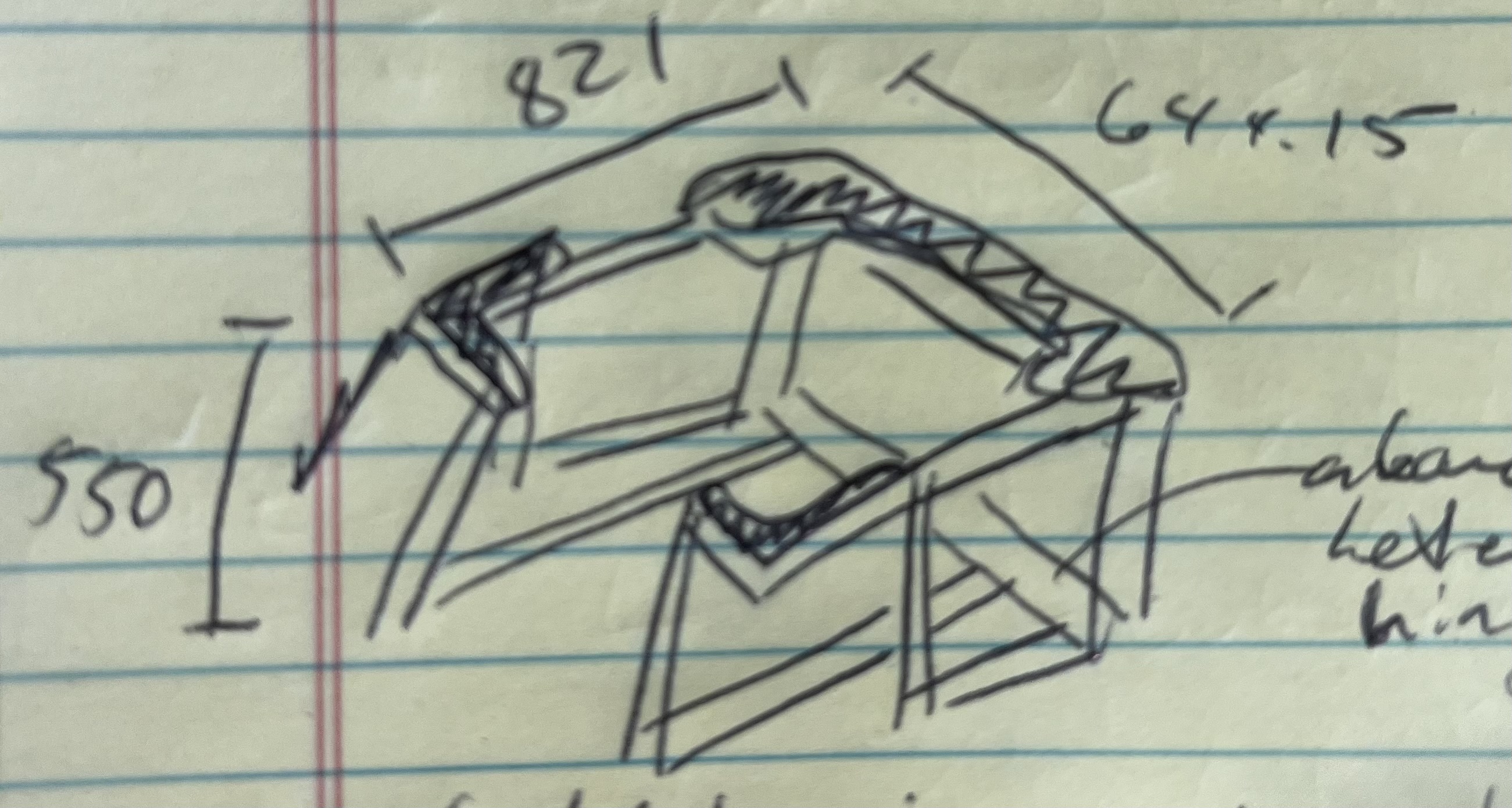
At Clarapath, one of my responsibilities was testing the various subassemblies of the final product. One of the most tricky parts to test was a large gantry assembly, because in order to test it the gantry had to be flipped on its back, thereby working against gravity and compromising the integrity of the test.
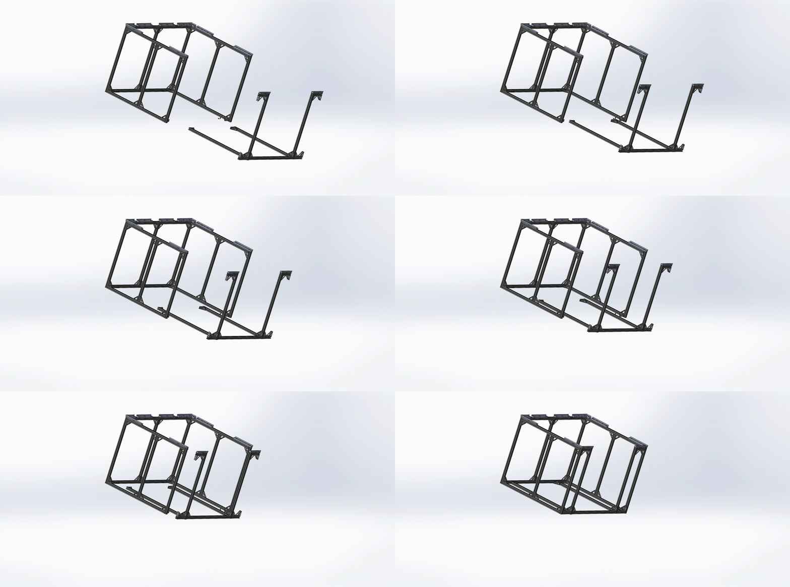
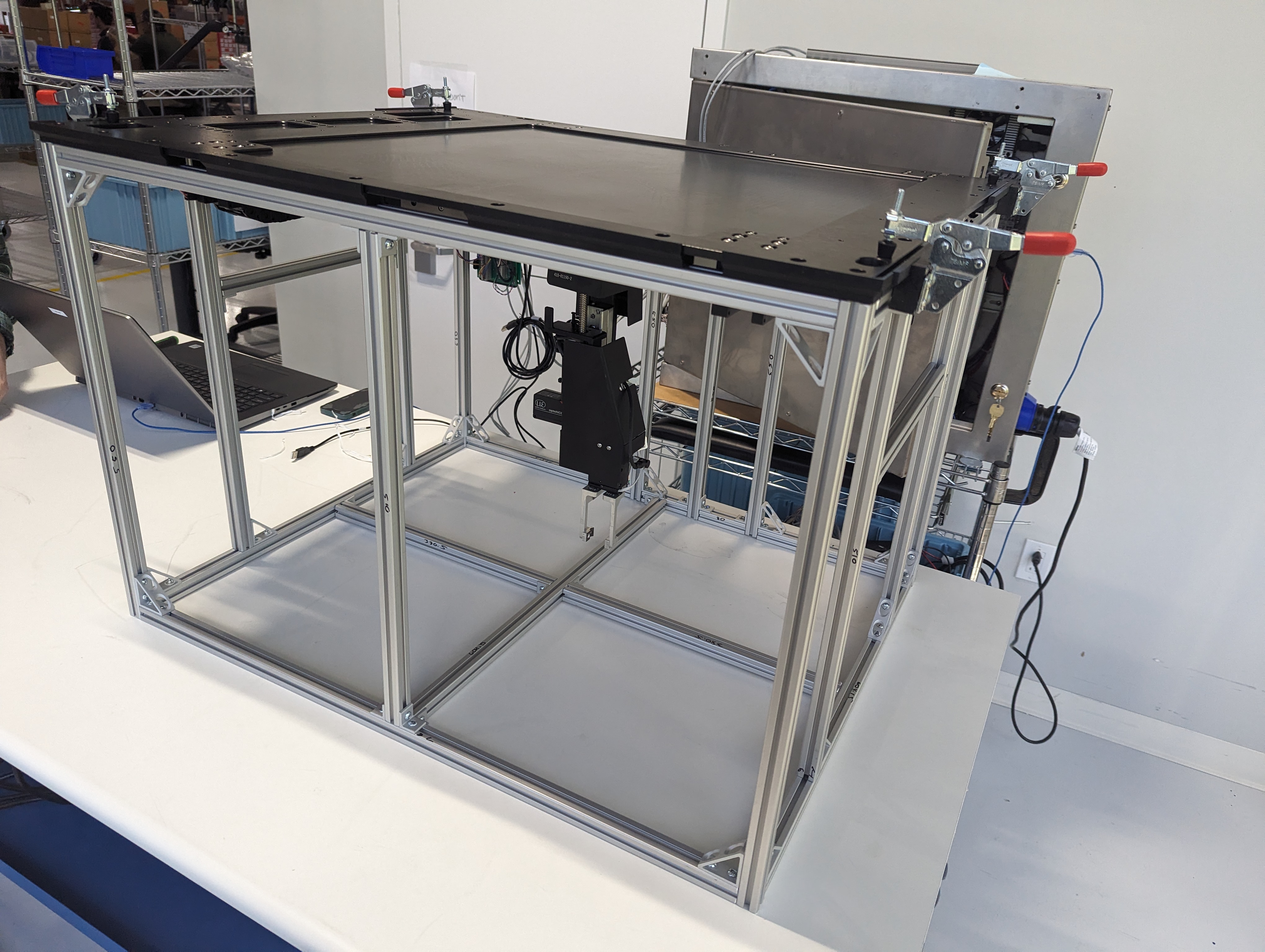
To fix this issue, I designed and manufactured a test ficture from 8020 aluminum bars, aluminum gussets, and 3D printed plastic faces which serves to hold the gantry up in the correct orientation while the test is performed.
The Design Process
To solve this engineering problem, I utilized my skills in...
- Solidworks: I modeled the assembly before putting it together, using the software to ensure my design made sense before constructing it in the real world.
- Rapid 3D Printing Prototyping: Utilizing the files I created in solidworks, I was able to download stl files which I could then 3D print. Observing the flaws in my model (made more obvious by viewing them physically), I made several rounds of edits to my design.
- Machine Shop Tools: To put the device together physically, I had to first use a chop saw to mark and divide the purchased aluminum 8020 into the desired lengths. Additionally, I used a belt sander to make the pieces easier to work with once they were cut by the rough chop saw.
Unfortunately, on assembly I ran into the problem that the vertical bars were not level by about 5mm. I fixed this by using a hand sander to shrink all the vertical bars to the shortest one. This worked out fine thanks to the extra 50mm of wiggle room I gave the height of the fixture.
Outcomes
The assembly currently resides at Clarapath, where it continues to be used to test the gantry subassembly. This project aided greatly in my more physical mechanical engineering skills, such as the machine shop tools and 3D printing. In the future I hope to be able to make more large assemblies like it.
